
OpenMaze PCBs/shields
A shield is an extra circuit board that stacks on top of the Arduino and provides extra functionality. Our shields contain connectors so that you can connect extra components like motors or solenoid valves, and the extra circuitry that is necessary to drive them. Because of the wide variety of components that people might want to use, we designed different versions of PCBs for different microcontrollers and that offer different connectivity. We also tried to make each version as flexible as possible, so that you can just connect what you need without having to redesign or resolder the board.
SEE PCB PRINTING PAGE TO LEARN HOW TO ORDER OM PCBs.
All OpenMaze PCBs have:
- at least 4 H-bridge outputs for 5V/12V solenoid valves
- connector for MPR121 capacitive touch sensor (able to sense 12 touch pads/lick ports)
- IR beam break detectors (x4)
- all spare arduino digital pins are broken out to "PGIO" ports, allowing connection of a variety of components with minimal wiring.
While we originally designed our first OpenMaze shields for the Arduino UNO microcontroller, our newest PCBs provide similar functionality for newer devices such as the ESP32 WiFi/BT enabled microcontroller and the Raspberry Pi single board computer. We still use the UNO PCBs for simple tasks, but check out newer boards for extended functionality.
OM PCB design (OMwESP32)

OM PCB (w. ESP32)

OM protoboard ( original)

Varieties of OpenMaze shields
Here are some OM PCB designs that we've created, tailored for a variety of purposes.
Click on individual boards for a description.
OM shield PCB variants (named by number of H-bridges):
-
OM1: This variant integrates with Matlab's Psychophysics Toolbox (from Dennis Pelli, NYU) to deliver visual stimulation for the OpenMaze Mouse Visual Operant task. Matlab handles the display of the stimulus; when the choice period begins, it sends a message to the Arduino telling it to start counting behavioral responses. OM2 will also work for this, but OM1 allows you to have more free pins for user modifiable features.
-
OM2: This is the standard UNO board with two H-briges, one with 2-wire stepper control and one with 4 independent outputs for solenoid valves.
-
OM3: Similar to OM2, but with three H-bridges so that you can control two stepper motors, in addition to four solenoid valves. This is useful for manipulating two different tactile stimuli simultaneously (not in current use).
-
OM4: This board is for use with the Arduino MEGA or DUE processors, that have scores more inputs and outputs than the UNO, and are broken out for use in a variety of different circuits.
-
OMwESP32(wireless): New board based on the Adafruit Feather ESP32 microcontroller. Allows wireless WiFi/Bluetooth connectivity.
-
OMrPi (RaspberryPi): New PCB for adding OpenMaze functionality to the Raspberry Pi GPIO pins
Basic design philosophy
When we design these PCBs, our aim is to make it as easy as possible to assemble a board to control a wide variety of mouse behavioral paradigms. For this reason we have adopted a few design principles:
1. Through-hole connections: makes it easy to solder by hand
2. PGIO ports: break out all microcontroller pins possible in an array with useful power and ground connections for each pin
3. H-bridges: use digital OUTs to gate a higher voltage to drive solenoids, motors, and fans
4. I2C/SPI digital communication: make plugs for common forms of digital communication with other ICs/sensors/devices.
When I first began experimenting with open-source electronics I used a standard breadboard and jumper wires for connections, but found that such a setup made for unstable connections that often became disconnected with frequent use. Using a protoboard with soldered internal connections and 0.1" headers for external connections made the system much more stable, but we soon needed to make individual customized boards for different behaviors. While we originally designed the OpenMaze PCBs to control a somatosensory operant task for mice, we quickly realized that with a little work, the shields could be formatted to control a wide variety of other behavioral paradigms. The main way we do this is by breaking out as many of the Arduino pins to a multifunctional bank of connectors, what we call the PGIO, or "Power-Ground-Input/Output" banks. While the Arduino controls the logic for running the behavior, you need to connect it to various electonic circuits in order to actually do anything. Since most modern digital components (e.g. sensors or servo motors from Sparkfun) require a digital input/output, +5V power, and GND, but in a different order, we designed the PGIO ports to allow every possible combination of these connections, simply by plugging a female headers into a different combination of adjacent holes on the PGIO bank row.
In addition, the primary components we use for our behavior, the H-bridges we use to drive stepper motors and control solenoid valves for water rewards, can also be used for a number of different purposes.
The standard shield: OM2 (for Arduino UNO)

OM2
This shield, named OM2, is the one most commonly used in our lab. It provides the following features:
-
Independent control over four different solenoid valves, for delivering water rewards, air puffs, olfactory stimuli, or gustatory stimuli
-
Control over a stepper motor, for instance, to bring a tactile stimulus into the whisker field
-
Touch or lick sensing
-
Digital output lines, for controlling servo motors, linear actuators, or speakers
-
Analog input lines, for monitoring stimulus position, voltages, etc.
Like all our shields, you decide which of these features you want to use. By connecting the inputs and outputs to the appropriate components (see the Components section), and by programming the Arduino to control those components (see the Software section), you can produce a huge variety of specific behavioral tasks.
Building a behavior with OM2
1. Order PCB
To make OM2,, order a printed circuit board (PCB) using the instructions here. You don't need to do any wiring because the connections are already printed on the PCB.
2. Design behavioral task: Write down components needed for the behavior, and assign the functions to available microcontroller pins.
3. Assemble PCB with desired components
After you receive the board, you need to attach the components. Solder the components in the holes that are marked, and they will already be connected.
Here is a basic parts list. See our components section for more information on what each of these components does.
-
Two H-bridges
-
Two IC sockets for the H-bridges to sit in
-
One MPR121 (from Sparkfun; optional, only for touch/lick detection)
-
Long strip of 0.1" headers (plugs and sockets), which you can cut to size
-
Two BJTs (NPN transistors, like the 2N2222A)
-
Two 10K resistors and two 1K resistors
We use 0.1" header as a standard connector. These are the 1x4 and 2x4 boxes labeled "Stepper" and "Solenoids" on the diagram.
You can read more about the BJT/resistor circuit for controlling the stepper motor here.
4. Assemble components for behavior.
Different behaviors will require different electromechanical devices such as
Sensory stimuli:
- speakers for auditory stimuli (such as simple tones from an arduino)
- LEDs for visual stimuli
- solenoid valves for olfactory or gustatory stimuli
- motors or solenoid valves for whisker stimuli
Animal actions:
- levers for lever press choice
- IR beam break detectors for nose pokes (included on some boards)
- capacitive touch sensing (either via MPR121 or built-in touch pins on ESP32)
Feedback:
- solenoids for liquid reward
- motors for pellet dispensing
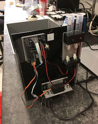
OM2 PCB (w. Arduino UNO) driving 2 channel gustometer box
.jpeg)