


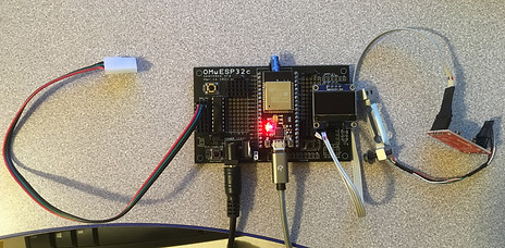
OMwESP32 shield
(order OMwESP32 from OSH Park)
This is a new PCB for use with the ESP32 microcontroller, which has native WiFi and Bluetooth capability (cool right?).
The ESP32 microcontroller is faster than the typical arduino, has a separate core dedicated to WiFi/BT, and also works with the Arduino IDE. Even more importantly, it has a large and growing network of developers so like the arduino it's generally easy to find answers online.
OMwESP32 is similar to our basic OM2 board with the following features:
- one H bridge set up to drive a single stepper motor (e.g. for a whisker stimulus), four solenoids/fans, or drive two bipolar motors forward or backward.
- one Darlington array IC (ULN2803) able to control up to eight 5V/12V solenoid valves (for liquids or air), fans, high power LEDs, etc.
- lick sensing via the MPR121 capacitive touch sensor
- speaker output for cue tones (generated by the ESP32 "ledc" functions)
- servo motor output (e.g. for driving linear actuator to move stimulus or lick port into place)
- breakout plugs for I2C and SPI (with dedicated OLED screen plug).
- built-in buttons for easy input
- Our standard PGIO (power-ground-IO) ports that make it super easy to plug in a variety of different components.
The basic idea of OMwESP32 (and all of the shields we've designed) is to connect the various inputs and outputs on the microcontroller to external hardware, such as sensors or valves. Then, you can program the Arduino to control this hardware in a variety of different ways, depending on the specific behavioral task you want.
The main difference is that the ESP32 board also allows wireless program upload and data streaming (I've only used WiFi thus far but Bluetooth is also possible). I will try to upload sample code for these functions soon, but contact me if you're interested and I haven't yet gotten it up.
Like our other shields, OMwESP32 is loaded with different components (resistors, transistors, integrated circuits or ICs, etc.) which are wired into the inputs and outputs.
Components List
-
One ULN2803 Darlington array IC
-
One 16-pin, one 18-pin IC sockets for the H-bridge and ULN2803 to sit in
-
One MPR121 (optional, only for touch/lick detection)
-
Long strips of 0.1" headers, which you can cut to size (mostly female)
-
soldering iron and solder
-
2.1mm barrel jack connector (breadboard compatible)
-
5V voltage regulator (if running wirelessly)
Making the shield
To make the OMwESP32:
-
Order the printed circuit board (PCB) from OSH Park. Current price is $50 for 3 boards, although you can get them made cheaper elsewhere but have to upload the design file ZIP in the correct format.
Attaching the components
Once you have all the components, simply solder them into the shield. Place the components in the holes that are marked, and they will already be connected appropriately.
Using the shield with the ESP32 and Arduino IDE
Using the ESP32 with the Arduino IDE requires download of board-specific information so follow these instructions.
IMPORTANT NOTES:
-
There are a few different versions of the ESP32 development board, so check the pinouts and make sure they are compatible with this shield (3v3 at the top left, 5v at bottom left). This is the "dev kit C v4" layout.
-
Normal devKitC is wider than the NodeMCU layout so I added two sets of holes, but pinout is same.
-
Also, note that some ESP32 versions like these may need a capacitor between Reset and GND so you don't have to hold down the boot button while uploading. I also put a special plug on the PCB just below the ESP32 for this.
-
The typical ESP32 package is the WROOM, however the WROVER is just a bit more expensive and has more memory which allows you to store more data and hold larger programs and libraries.
-
ESP32's PWM functions are a bit weird in that they use an LED dimming function called "ledc". There are examples online for tone functions using this.
New November 2021
I've just completed two new smaller ESP32 PCBs, the OMwESP32small and OMwMini. They don't have all of the multi-functionality of the full boards but have a reduced footprint while maintaining more basic OpenMaze functions. More to come!
ALSO
I've been working on wireless data transmission with the ESPnow protocol, which promises to be the easiest method of wireless data transmission. More to come on this soon.